
SONY VAIO VGN series VGA rework
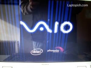
Here we have SONY VAIO VGN-FZ21M. When is turned on, on the first screen we see blue lines, as show on the picture.
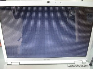
After this, when the laptop do the usual self tests and we see a black screen with white letters, instead of seeing that we see a white vertical lines, as shown on the next picture.
This suggest that we have a problem with the Graphic card and we need to make a rework of the graphic card chip.
So we begin to disassemble the laptop.
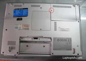
After removing the cover of the Hard Disk, next we remove the hard disk.
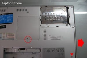
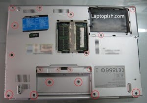
On the previous picture with the red circle is assigned the screw that need to be removed so how the RAM memory cover can be removed. With the small is assigned the screw that hold the optical drive. After this screw being removed, in the direction of the big arrow we remove the optical drive.
On the next picture with the red circles are assigned the other screws that need to be removed from the bottom.
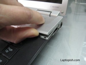
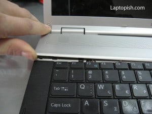
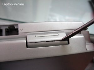
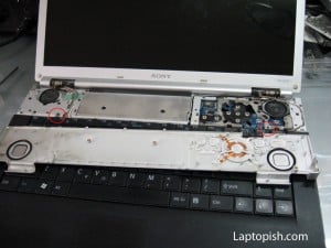
After this we can remove the bezel from the upper side, as show on the pictures, first raise on the both sides, and later from the back side.
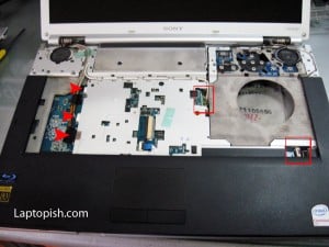
After this we remove the bezel and can remove the keyboard, but first need to be removed the two screws, assigned on the next picture.
When the keyboard is removed, we need to remove the flat cables, as shown on the next picture.
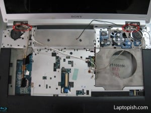
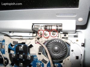
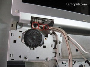
When this is done, we can remove the screen assembly, but to do that we need to remove the screws assigned on this picture.
or if we see little closer on there are by three screws on the both sides.
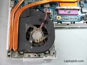
After this the screen assembly is removed, and now we can remove the bottom cover also, and we have this:
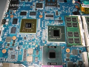
In the previous picture we see the reason for failure of the laptop. The dust collected on the cooler make the laptop come to overheating.
On the next picture are assigned the screws that need to be removed so how we can remove the cooler.
After the cooler removed, we can remove the fan, as assigned on the picture.
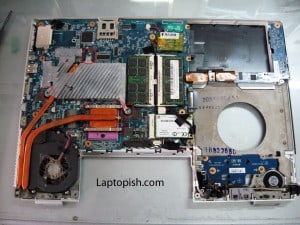
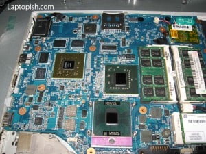
Next before we can do the rework, we need to clean the chips from the old thermal silicone paste. On the next picture we have cleaned the motherboard.
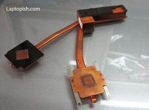
Also the cooler need to be cleaned.
After the rework of the graphic chip is done we wait the board to cool down.
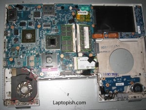
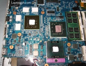
After that we apply the new thermal silicone paste as show on the next picture. The thermal adhesive are applied on the appropriate places.
After this we mount the cooler and assemble the laptop with the procedure backward than this shown here.
1 Comment
hi
very interesting. I have a rework station (controlled hot air flow).
Did you use similar way to fix the probelm. Could you better describe the “rework” process that you use? Does the rework fix the problem?
What is the time/temperature profile that you apply?
BR
Bageera