HP Pavilion dv6500 CPU cooler replacement
HP Pavilion dv6500 is a good series of laptops, but have a common failure: because the cpu cooler is very hard to clean (you have to disassemble the whole laptop so you can clean the cooler), so that’s why come to the overheating of the Chipset or the GPU. The cpu cooler is essential for providing a good cooling of the laptop. So, that’s why here we gonna show the procedure how to replace the cpu cooler of the laptop, step by step.

First we should do is to remove the battery and the power source from the laptop!
After that we begin with removing the covers of the RAM memory and the Hard Disk Drive. To remove this covers, we need to remove the screws assigned with the red circle on the next picture. With the red arrow is assigned the screw that hold the Optical Disk Drive.

After removing the screws and the covers, we can remove the Hard Disk Drive and the Optical Disk Drive, as assigned on the next picture.

Next we remove the screw assigned with red circle, and detach the WLAN anthenas from the WLAN card, assigned with the red arrows.

With the red square is assigned CMOS battery. If you need to reset the BIOS of the Pavilion dv6500, you just remove the battery, and short circuit the pins for five seconds.
There are three screws under the optical disk drive that need to be removed.

Next we need to remove the keyboard. So we need first to remove two screw from the back side that are placed under the battery.

There are one more screw that hold the keyboard and three others that hold the power button panel.

After that we remove these two screws:

Now we flip the laptop and raise the power button panel, so we can remove the keyboard as shown on the next few pictures:


We raise the keyboard and remove the flat cable in the direction of the red arrow.

Nest we remove the flat cables that go to the power button panel, in the direction of the arrows.

The flat cable assigned with number “1” connect’s the power button with the motherboard, and is common failure. If this cable have a break, the laptop will don’t turn ON at all. The flat cable assigned with number “2” connect’s the motherboard with the touch multimedia buttons. The both cables are identical, so if you don’t have a spare cable for check, you can use the other. (It’s better your laptop to run without multimedia touch buttons, unlike that don’t run at all).
Next, finally remove the power button panel, but before that we need to remove this cable:

The WLAN antennas removed early from the WLAN card:

now should be released from the fixed position, so we can detach the screen assembly.

We remove the cables assigned with red circles and we come to this situation:

The screen assembly is holding by four screws. The form the lower side and two from the upper side. First we remove the two screws from the lower side:

and later we remove the screws from the upper side:


with the red arrows are assigned the screws that hold the screen assembly. With the red circle only is assigned a screw that hold the upper bezel. With the red square is assigned the Flat cable for the monitor.
Now, we can detach the screen assembly, and now we have this:

There are two screws that need to be removed and we continue with the removing of the screws from the lower side:

There is one screw left so we can remove the cover under the screen assembly:

Next we remove the flat cable that connect’s the touchpad:

After that we can remove the cover:

As shown on the previous picture, now we need to remove the screws that hold the express card slot and the cable that connect the bluetooth to the motherboard.
After that, we can raise the motherboard a little and remove the power cable (the cable that connect’s the power jack to the motherboard), and the cable that connects USB connectors on the right side to the motherboard. We remove the both of the cables in direction of the arrows.

After removing this two cables, we can raise a little more the motherboard and from the front side we can remove the cable that connect’s the 3,5mm audio jacks to the motherboard.
After that we can remove the motherboard completely.

Now we can remove the old cooler, by removing the screws assigned on the picture:

After that, we clean the contact surfaces, and before install the new cooler we put a silicone thermal paste, that improve the thermal conductivity between the surfaces.
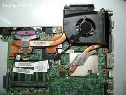
Here is the new cooler on the motherboard:

Now the job is done and only need to assemble the laptop. The procedure is the same as we shown here, only backward.
The only thing we need to take care is when placing the motherboard to look at the WLAN switch, as shown on the picture:

Leave A Comment