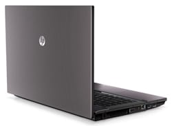
HP Compaq 620 LCD screen replacement
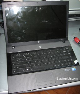
Here we have a HP Compaq 620 laptop with a broken lcd screen.
Usually for the HP laptops, for replacing the lcd screen need first to detach the screen assembly. But with this model we gonna try to replace the screen without detaching the screen assembly.
First, we remove the power source and the battery for safety.
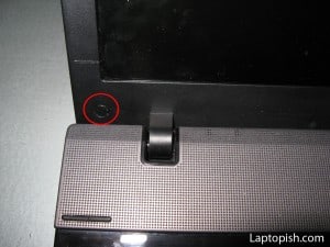
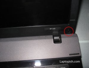
There are two screws that hold the front bezel of the screen assembly. First we remove the screw covers, and after that the screws, as shown on the next pictures.
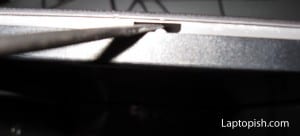
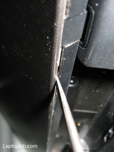
After that, we begin to separate the front from the rear bezel. First the upper section:
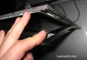
Later the bottom section:
But, in this point, we see that we can’t remove the lcd screen without detach the screen assembly.
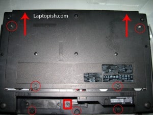
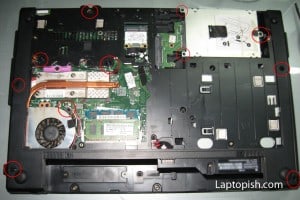
We begin with flipping the laptop with the bottom up. On the next picture with the red circles are show the screws that need to be removed.
With the red square is assigned the screw that hold the power button. Do not remove this screw! After removing the assigned screws, we remove the bottom cover, and we have this situation:
On the previous picture, with red circles are assigned the screws that need to be removed: three screws for the Hard Disk Drive, one screw that hold the CPU cooler, and seven other screws.
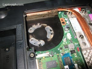
When we come to this point, is good to clean the CPU cooler.
After that, we can mount the cooler back to his position.
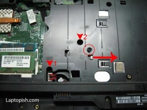
Next we need to remove the keyboard. To do this, we need to remove this screws:
assigned with “1” and “2” on the previous picture. With the red circle on the previous picture is assigned the screw that we need to remove, so we can remove the DVD-RW drive. First we remove the screw and then we remove the DVD-RW drive in the direction of the red arrow as assigned on the picture.
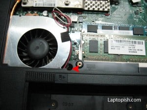
Next we remove one screw that hold the keyboard near the cpu fan.
Under the removed DVD-RW drive, there are two more screws that hold the keyboard.
On the side of the removed DVD-RW drive, there are three screws that need to be removed.
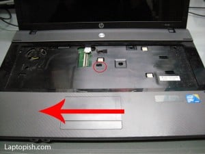
Now we can remove the keyboard. Be careful with the flat cable. After that we have this situation:
We remove the screw assigned with the red circle, and after that we remove the cover in the direction of the red arrow. But be careful with the flat cable for the touchpad.
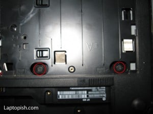
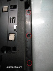
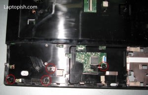
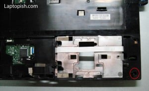
Under this are another screws that need to be removed, as shown on the next two pictures.
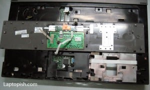
Now we can remove the plastic cover. Be careful with it. Special attention require the 3.5 mm audio jacks.
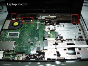
When the plastic cover is removed, we have this situation:
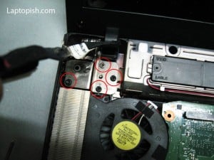
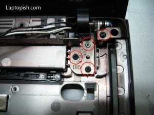
With red squares are assigned the flat cable for the monitor and the brackets that hold the screen assembly and need to be removed.
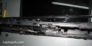
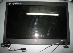
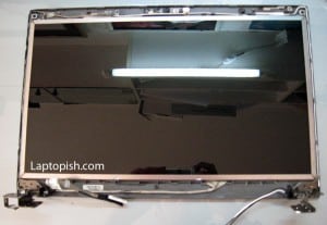
After removing the screws assigned with the red circles on the previous two pictures, the screen assembly is free and can be removed:
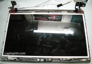
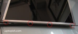
Now we can easy remove the front bezel. After that we need to remove the screws assigned on the next picture, so we can release the LCD panel.
After removing LCD panel from the bezel, we need to remove the brackets. There are by four screws on the each side.
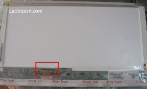
After that we remove the old display. The new display is shown on the next picture:
With the red square is assigned the place where we connect the flat cable removed from the old LCD panel. This LCD panel is LED, so it has only a flat cable connector (unlike the standard LCD panels that have also jack that connects to the inverter).
After that we mount the brackets, and attach to the bezel.
After that we mount the front bezel, and the rest of the procedure is the backward of the procedure shown to this point.
2 Comments
Thank you! Excellent post on an excellent website. It taught me how to do this properly!
vary good thanks